donderdag 13 oktober 2016

BX23 flight day


[Photo credits of the aurora before the BX23 flight: Michael Becker]

The day BX 23 took off, we had a count down starting at 3:30 AM.
All teams gathered at the dome (massive construction where gondolas are assembled) to finalize preparations and run the usual last tests before launch.
Things are tense until the very last minute, and the four hours countdown can easily last five hours and a half.
But nobody would ever complain: we are there, and our sweat and tears of the last year are about to fly!
Less than one hour before the final lift-off, the late access team comes back, after removing the covers from our solar panels. This is the last we could see OSCAR up close before the launch.
The last full three quarters of hour, the whole bunch of the BEXUS campaign participants stayed at the entrance of the dome, super excited while they witnessed a perfectly nominal balloon inflation and lift-off.
After nearly five hours, the cut-off sequence was initiated. We managed to gather a huge amount of good data until our battery dried out, shortly before the descending.
Less than 24 hours later, we could meet our experiments again, when the recovery team brought our gondola back. You can imagine our surprise when we saw that OSCAR's frames withstood the fall (through some tree branches, even!).
More info and many more photos will follow!
For now: Thank you!
ThanX to all those who supported and helped us during this intense year of preparation! It was worth every minute of work!

donderdag 6 oktober 2016

Campaign week process

After 5 days of work, OSCAR is ready and fixed on the gondola!
The last few days have been very very tiring, with a lot of mounting and testing to do, and the occasional ghost hunt for to resolve problems that were never really there... We troubleshot so much in the last month, that we cannot believe that we do not have anything else to fix!


Make sure to keep an eye on our facebook page to follow our adventures :) In the meantime, we will take as many pictures and videos of our countdown and launch as possible! Like this we can report back soon and show you the payback of an entire year of work.

zaterdag 1 oktober 2016

Campaign week has started!

After roughly one year of work, our team has finally made it to the end!
We packed the rest of our experiment in an awesome BRAVIA 55' TV box (just to make sure airport staff will treat it as gently as possible) and got on the plane.
As soon as we landed in Kiruna, we could find again (almost) all the other teams members!
Get in for a group selfie, everyone!
Of course, first thing to do in the evening/night/early morning of our arrival is not sleep... We need to get used to heavy schedules, so: let us re-mount SAM-V3! Remember the awkwardly large magnetometer we once buried in the snow during training week? Well, he came with us once again, but needed some new tweaks, which J&J worked on till too late.

The North of Sweden looks different without the piles of snow. We left a white mass of land in February, to find a green forest! That means a whole new set of activities possible for our free time!
... but will we even have any?
For now, we are busy assembling all components back, fixing last minute changes, and trouble shooting for the last time.
Keep tuned, as we will try to share our progress as frequently as possible in between the rest of the campaign preparations!

woensdag 21 september 2016

There it goes...

OSCAR finally left UHasselt, in a very heavy and sturdy wooden box.


... bye bye, baby Aury!

See you in Kiruna!


dinsdag 20 september 2016

S.U.Z.Y. meets OSCAR

Our experiment passed its last review, and is finally ready to fly.
With this news, a lot of local news channels and science enthusiasts got really interested in us, and that's how we ended up not only on the local TV channel TV Limburg and in the national news paper Het Laatste Nieuws...

... but also tagged on Stijn Meuris' photo!


It was quite something to meet the man who sang about lovely satellite S.U.Z.Y, spinning quietly above the Earth and watching us from a distance.

Tot binnenkort, S.U.Z.Y!

woensdag 7 september 2016

Work work work work work....

Neverending work in space business!
Even if you actually stop at the stratosphere ;-)

Our electronics team needed to assemble lots of tiny components on our very cool Printed Circuit Boards (PCBs), which are those fabulously practical sheets that hold all our connections. Since all the resistors, capacitors, amplifiers, and other elements of the circuit were not there yet, someone needed to spend long hours to position them on top of the right connections, paste them in place, and then "bake them" (the correct term is "solder") in order to create the link between the component itself and the electrical pathway hidden inside the PCB.

This requires quite some patience, good eyes, and a whole lot of time!
That's why we had an overkill of footage for this little timelapse video about the PCB finalization process.

The second head you see in the video is Thijs Vandenryt's, a brilliant engineer who volunteered to help us! Thank you Super TV!

donderdag 1 september 2016

... and this is how Aury was born!

A while back we learnt about how circuits are born.

Now it is time to praise the team who brought Aury up!

Our magnetometer is basically ready to fly, and that is because Jarda and Jelle (J&J) dedicated a lot of hard work and sacrifice to their little creation.

Here on the left is a very 'early' photo of Aury, when she was still a baby magnetometer, and needed to be connected to a few expensive lab tools to operate.

During the last few months, J&J made it possible for her to fly with her own equipment, designed especially to be light weight and "inexpensive" (she is still quite precious), and perfectly fit for the application we need.

The principle to probe the magnetic field is based on the splitting of degenerate energy levels, their photoluminescence, and the visualization of the whole process via the dips in the intensity of the exciting microwaves.
Before you get your minds in the gutter for this last element, make sure you refresh your memory on how we can use diamond to sense the magnetic field...

So, we need a microwave excitation to split the energy levels, a laser and a light sensor to create and detect the photoluminescence, and of course a lot of electronics and software to write down in files what is happening, so that we can look at the data afterwards.

This translates into having to "break down" the voltage, in order to power up the various components, which is done with the circuit on the left, then generating the frequency which will "time" the entire setup through the means of a square signal wave, which is handled by the circuit on the right, and of course in driving the laser correctly (which means making sure it always gets the right amount of current).


The only two commercial components which will fly with Aury are those which generate the microwave sweep itself (the timing of it is given by the home-built square wave signal generator).

But now, where is the actual diamond in all this?

It's where you see the green of the laser shining... right in her heart!


And beware, this is her last naked photo: she will get a nice dress by the time she will fly, because she won't be a little girl anymore!

P.S.: our testing also continues... on Youtube!

donderdag 11 augustus 2016

This is how circuits are born

It is due time that we celebrate our engineers/magicians, who are the actual reason why OSCAR has survived all this time.
Let us keep the magnetometer aside for now. A dedicated explanation of how that works will come on a separate blog post. If we focus on solar cells, you may remember that we talked about measuring their efficiency a while back.
The famous Current-Voltage characteristic you heard about back then, is exactly what we want to obtain for each of our devices while they fly. Those characteristic curves are made by couples of Current and Voltage values, collected -for example- by applying Voltage X (in water analogy, this was the pressure), and reading the current Y that "comes out" of the system (or the flow of water through the pipe).
Sounds easy enough, but it is actually quite complicated to do it, if you have to design the whole circuit...

This is where Steven (forgot about him?) came to save us.
He is designing the measurement instrumentation for us. Roughly, this means that he has programmed a little computer chip to send specific signals to a net of amplifiers, resistors and capacitors. These signals, just like the whole circuit components web, are finely tuned to make sure that the correct Voltage is selected, and that the readout of the Current is accurate and within the limits that the computer chip can withstand without breaking.
Why do we have to be so precise?
Home-built dedicated circuits are normally cheaper than the fancy equipment we would have in a laboratory. That's why we can actually afford to mount them on the balloon and let them crash -maybe very harshly- at the end of the ride. Lab tools are also very heavy and require way too much power to operate... Really not fit for flying with the BEXUS!
They are of course designed to handle a very large variety of "situations" and to be used for many different applications.
That's one downside of our cheaper setup: it does not have such flexibility. We have to build the safety measures ourselves, to make sure we do not let too much current in the chip, for example, or to avoid overheating amplifiers.


But calculating the needed components for the wanted ranges of operation is not all!
You might remember that we want to test a few different kinds of solar cells... As a total, we are going to mount photovoltaic devices from six different materials on our BEXUS gondola!
What does this translate to?
Six times the requirements for operational ranges, six different layouts for the pins with which we need to apply the Voltage and read the Currents, and a whole lot of cables and connections to take care of!
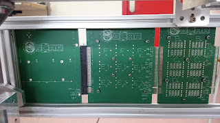
But Steven fixed this, as well: he packed all the cables in some extremely pretty Printed Circuit Boards, which are like thick sheets of copper and insulators, and contain the various connections within them, on separate layers. They also have a shielding copper plate, to avoid signal distortion.
Can you believe that there are the equivalent of 149 cables in these green sheets?


OSCAR's logo is there, you will notice.
This is because our engineers are actually artists at heart ;-)

Now, the work is far from done... the PCBs contain the connections, but they don't have the contacts for the devices on them, for example. And attaching all those tiny pins is quite tedious, besides being potentially dangerous!


PS: have you checked out the short musical version of this story yet? It's on our Youtube channel!

donderdag 4 augustus 2016

Integration Progress Review highlights

Last week, we had our Integration Progress Review, also called "IPR".
Like for all space projects, the entire process needs to be constantly monitored and reviewed, to make sure things are going smoothly.
Also for REXUS/BEXUS projects, we are constantly supervised by our sponsoring agencies, who make sure that we are on schedule and that nothing is unaccounted for.


So... we mounted our experiment on a mock-up of the gondola (the metallic cubic frame which will be attached to the balloon), and it looks like what you see in the photo above! Say "Hello!" to OSCAR!

During the meeting, the entire team had the chance to meet our ESA mentor, we discussed the progress with the BEXUS 23 payload manager (who is particularly concerned about the safety hazards related to our experiment... not many!).


The experts brought with them a spectrum analyzer, as well, which allowed us to test that our home made Radio Frequency sweep is staying within the range we need to measure the magnetic field. We can thus be certain our measurement (between 2.82 and 2.9 GHz) does not disturb the data transmission to ground (around 2.4-2.5 GHz)... we and the other teams sure need the data to come down!


We can not yet lay back and relax. The newt review is scheduled for mid September, just before flight! By then, everything needs to be ready!
But in the meantime, we can release some stress over a nice beer with ESA mentor!

donderdag 28 juli 2016

Testing our way to IPR

IPR (Integration Progress Review) is coming up TOMORROW.
This means we really need to get our experiment ready for flight, and one of the most important things for space-related missions is: TEST!
Make sure you beat Murphy's Law! ... or at least limit its power as much as you can.

Among the various things to verify are: will our experiment withstand stratospheric temperatures and pressures? Will it withstand vibrations? Ans so on...


OSCAR: "How do we test vibration?"
Experts: "Living in Belgium? Just drive around on any road with your experiment in the back of a truck!"

... And so we did!


We also started testing our magnetometer (Aury). Jarda and Jelle did an awesome job in building her up, and she has already passed our vacuum testing.
See her inside the vacuum bell? She worked for over 5 hours at a pressure of 20 mbar.
Way to go, Aury!


Cross your fingers for us, you all: tomorrow's review is a crucial step towards our balloon flight!

donderdag 30 juni 2016

And the OSCAR for the highest power-to-mass ratio goes to...

On the 10th of June, professor Jean Manca (who is endorsing our OSCAR project) gave a talk with this title to the 2nd Dutch Perovskite Workshop.
The event, organized in Delft, aimed to reunite the "perovskite community" within the Netherlands and neighboring countries, to discuss about the progress of research on hybrid perovskite materials (mainly for solar cells applications).

But what are these hybrid perovskite materials, exactly?

The word perovskite itself defines a kind of crystalline structure, which is typical of calcium titanate. The same structure is found on various kinds of materials, with applications ranging from superconductors to batteries to... solar cells. The reason why we refer to hybrid perovskites is because (in perovskites used for solar energy conversion) one of the building blocks of the crystal, the central dark sphere in the figure, is an organic molecule. Hence, we are back to carbon-based!
What is so special about these materials, apart from the fact that they are partly organic and partly inorganic?
They happen to be very fit for photovoltaic applications, as their permittivity ( remember, from some weeks back?) and their charge carrier mobility are quite high. This means that charges promoted to the Conduction Band are immediately separated from the Valence Band, and that they can move very fast to the collecting electrodes and to the outer circuit.

Besides these electrical properties, hybrid organic-inorganic perovskites also have a high absorption coefficient over a broad spectral region, which means that they can absorb light of all visible colors (and also some "invisible colors", like infrared and ultraviolet)... and lots of it!
The high absorption coefficient is a characteristic that hybrid perovskites share with some of their all-organic cousins, and it represents the main reason why solar cells made out of these special semiconductors can be fabricated from very very (let us say "ultra") thin layers.

Going back to outer space applications, we should consider that the cost to bring (anything) far enough from the Earth as to escape the gravity pull is extremely elevated, and scales up with the weight (or, more precisely, the mass) of what we want to send up.
Therefore, it is a smart idea to optimize the mass of the devices we will need on our space bases or space ships, in order to save some money in the transport process.
Here is where ultrathin perovskite solar cells outperform all other rivals.
Perovskite solar cells have higher efficiencies than organic solar cells, but they still do not beat the very expensive inorganic ones in terms of pure power conversion efficiency.
But to look at it from a fairer point of view, we should consider the power that solar cells are able to generate per unit of mass: the power-to-mass ratio!
With this new parameter at hand, we can compare photovoltaic technologies based on their compatibility with "out of Earth's orbit" applications, and we can finally convey the real drive behind our desire to test the reliability of organic-based solar cells in extreme stress conditions.

As a little side note: ultrathin OPV (Organic PhotoVoltaics) are a close second to perovskites... that is why we decided to study them, as well!

donderdag 23 juni 2016

Let’s measure solar cells efficiency!

After clearly discussing how organic solar cells convert light into electricity, let us look at how to quantify the efficiency of this process.
Taking one step back, efficiency can be defined as  the ratio between the total generated power (output) and the total light power incident on the device (input), as was already explained in the post “Why carbon... solar cells?”.
But when it comes to actually measuring this, what are our options?
We will refer to the fact that the power generated (or consumed) by any electrical appliance is given by the product of the Voltage drop over the appliance and the Current passing through it.
To understand this in simple terms, let us take a hydraulic circuit analogy: the Voltage corresponds to the pressure of the water inside a pipe, the Current represents the flow of water through that pipe, and the Power is that generated by a mill set in motion by that same water.

If we have no pressure in the tube, the water will not flow out, and there will be no power generated by the mill. If we have no flow of water through the tube (because it is sealed, for example), regardless of the pressure applied, the mill will still produce no power. We can only have an output power for combinations of water pressure and water flow that set the mill in motion!
For solar cells, it works exactly the same way: we will need to look at the power generated for “good combinations” of Voltage and Current. To find these “combinations”, we need to know the relationship between Current and Voltage in our solar cell. That is: we need to know what Current we will get out of it, if we apply a certain Voltage (back to water analogy: what is the flow we can have out of the pipe, for a certain applied pressure?). This kind of relationship is called a Current-Voltage characteristic.

Such a characteristic can be plotted in curves like the one above.
How do we read such a curve?
The top quadrant corresponds to Power Dissipation, because we can see that by multiplying the Current value for each point on the red curve with the corresponding Voltage value, we obtain a negative “generated power”, which corresponds to a positive “consumed power”. Be careful, sign conventions may vary... just keep the concept in mind!
In this region, the solar cell does not produce any power because no light is shining on it.
Once we turn the light on, the Current-Voltage characteristic changes into the light blue curve, which now represents Power Generation (because, taking the product between Current and Voltage in the bottom quadrant, we obtain a positive value). Of course, the more intense the incident light, the more power the solar cell can generate, as we see with the darker blue curves.
But don’t be fooled: the solar cell produces more power... but there is also a greater input power from the light!
So, in general, the efficiency of a photovoltaic device can be determined for whatever amount of light we use to promote power generation.

This is, again, a simplification. Defects in the materials (quite often present in organic layers)  can lead to changes in the shape of the characteristic curve for various light intensities. In such cases, the ratio between output power and input power will not necessarily remain constant for varying intensities of light.